Pressure is the defining variable of a high pressure reaction, and yet the instrument measuring it is often the last thing specified and the first thing blamed. Two reactors running the same chemistry can give different kinetics simply because one has a gauge reading to the nearest 5 bar and the other has a transmitter resolving to 0.1 bar.
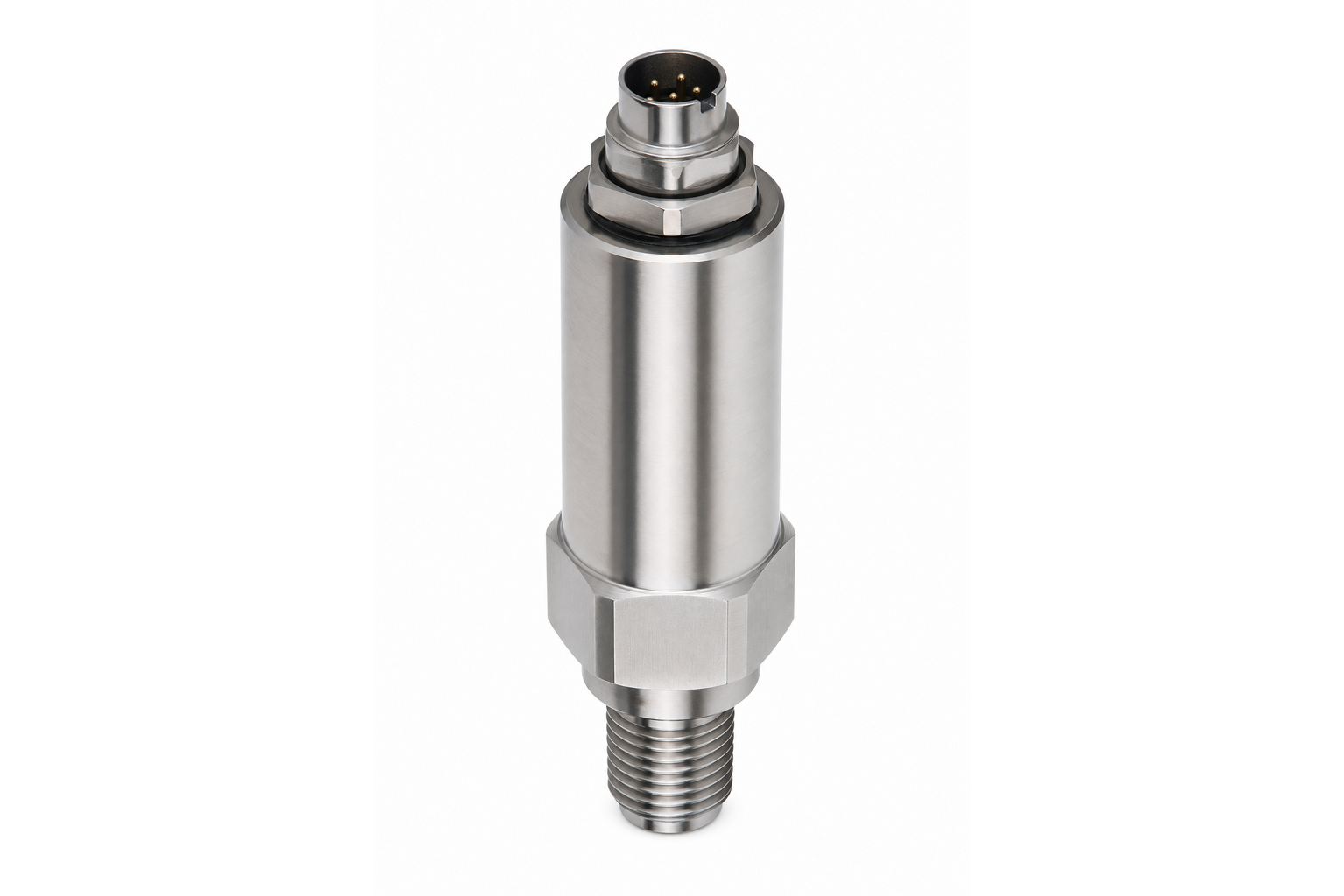
Krivalis supplies digital pressure sensors and transmitters from 1/4 in to 1 in connection, in SS316 or Hastelloy C276, rated at 100, 200, 350 or 600 bar, for service from −10°C to +80°C. This guide explains what those figures mean in practice and how to choose between the options.
First, the Terminology
These words are used loosely, and the looseness causes real specification errors.
- Pressure gauge: A purely mechanical display, usually a Bourdon tube with a needle. No electrical output. Fine for a local visual check, useless for data logging.
- Pressure switch: A device that changes state at a set pressure. It gives a trip or an alarm, not a measurement.
- Pressure sensor or transducer: The element that converts pressure into an electrical signal. The output may be a raw millivolt signal or a conditioned voltage.
- Pressure transmitter: A sensor packaged with the electronics to produce a standard, calibrated output — typically 4 to 20 mA, 0 to 10 V, or a digital protocol — that can be read by a controller or a data logger.
For a reactor with data logging or closed-loop control, a transmitter is what is needed. A gauge alongside it is still worth having, because a mechanical gauge keeps working when the electronics do not.
How the Sensing Element Works
Most laboratory and industrial transmitters use a diaphragm with strain gauges bonded or deposited on it. Pressure deflects the diaphragm, the gauges change resistance, and a bridge circuit converts that into a signal.
- Piezoresistive (silicon): The most common type. Sensitive, accurate and inexpensive, with excellent resolution. Silicon diaphragms are usually isolated from the process by a thin steel diaphragm and a fill fluid, and that isolation is what sets the temperature limit — typically 80 to 125°C at the sensor.
- Thin-film (sputtered): The strain gauge is deposited directly onto a steel diaphragm. Fewer interfaces, better resistance to vibration and thermal shock, and better long-term stability at higher temperatures. Common in rugged industrial service.
- Capacitive: Very stable and accurate at low pressures, widely used in differential pressure measurement. Less common for high range gauge pressure in reactor service.
For reactor duty at 100 to 600 bar, a thin-film or isolated piezoresistive transmitter in SS316 is the normal choice, with Hastelloy C276 wetted parts where the chemistry demands it.
The Specifications That Actually Decide Performance
Datasheets are long, but four numbers decide whether a transmitter will do the job.
- Range and turndown: A transmitter performs best in the upper part of its range. A 350 bar transmitter used on a process that runs at 5 bar is delivering a tiny fraction of its span, so the reading is dominated by noise and by the error terms that scale with full scale. Match the range to the process: the ideal maximum working pressure is around 60 to 80 per cent of the transmitter range.
- Accuracy as a percentage of full scale, not of reading: This is the single most misunderstood point. A transmitter quoted at ±0.5 per cent of full scale on a 600 bar range is accurate to ±3 bar anywhere in its range. Used at 10 bar, that is a 30 per cent error. Accuracy quoted as a percentage of reading behaves very differently, so always check which basis is used.
- Overpressure and burst pressure: The pressure the device can survive without damage or leakage, distinct from the range. A transmitter should tolerate a credible process excursion — a pressure spike on valve opening, or a thermal expansion event — without being destroyed.
- Long-term stability and temperature effect: Drift over months, and the change in zero and span as the sensor temperature moves. These are the errors that quietly accumulate between calibrations, and they matter more than the headline accuracy figure on a reactor that is never recalibrated.
Two further specifications matter for control: response time, which determines whether the transmitter can catch a fast pressure rise, and the output protocol, which determines whether it can talk to the rest of the system.
Outputs and Integration
- 4 to 20 mA: The industrial standard. Two wires carry both power and signal, it is robust over long cable runs, and a live zero at 4 mA makes a broken cable detectable.
- 0 to 10 V: Common on laboratory equipment and easy to interface to a data logger or PLC analogue input.
- RS485 / Modbus: Digital, addressable and able to carry diagnostics alongside the value. Useful where several instruments share one cable run.
- Switching output: A relay or solid-state contact that trips at a setpoint. Useful for an alarm or an interlock, but not a substitute for a dedicated safety device.
Wetted Materials and Connection
Krivalis transmitters are offered with SS316 or Hastelloy C276 wetted parts, with male NPT, socket or union connections from 1/4 in to 1 in, all full port.
Material choice follows the same logic as the reactor vessel. SS316 covers most aqueous and organic service. Hastelloy C276 is specified where chlorides, wet chlorine or strongly reducing acids would attack stainless steel. The connection size should be as large as practical: a small port is easily blocked by particulates, polymer or catalyst fines, and a blocked port means the transmitter reads nothing useful while still reporting a plausible number.
Note the temperature limit carefully. These transmitters are rated from −10°C to +80°C, and the 100 to 600 bar ratings are quoted at 80°C. A transmitter mounted directly on a reactor lid that runs at 200°C will not survive, and its reading will be wrong long before it fails. The correct fix is a standoff or a cooling extension so that the sensor body stays within its rated ambient.
Installation Practice
- Keep the sensor cool: Use a standoff, a siphon or a cooling element so the transmitter body stays under 80°C even when the vessel is far hotter. This is the most common installation mistake on reactors.
- Provide a snubber or restrictor: Rapid pressure spikes from valve operation or from a pump can damage the diaphragm. A restrictor smooths them out.
- Mount where it reads the process: A dead-ended port with trapped air reads low on liquid service. Orient the port so it self-drains, or purge it.
- Avoid mechanical stress: Do not use the transmitter body as a lever when tightening the fitting; support it and use two wrenches.
- Route cable away from heat and power: Separate signal cable from heater and stirrer power cable, and keep it clear of hot surfaces.
Calibration and Verification
A transmitter drifts. Zero drift is the most common, and it is easy to check: with the vessel vented to atmosphere, the reading should be zero. Many transmitters provide a zero trim for exactly this purpose; span adjustment is better left to a calibration laboratory.
For anything that matters, verify against a reference at more than one point — a dead-weight tester for high accuracy, or a comparison with a calibrated reference gauge. A single-point check at zero will not detect a span error, and a span error is what silently changes the kinetics of an experiment.
In regulated environments, the calibration interval should be set from evidence rather than habit: measure drift over the first two intervals, then set the schedule to match. Most laboratory transmitters settle into a stable pattern within a year or two.
Safety: What a Transmitter Is Not
A pressure transmitter is a measurement device. It is not a safety device, and it should never be the only thing standing between a reactor and an overpressure event.
Overpressure protection belongs to mechanical devices — a rupture disc, a relief valve or a bursting panel — sized for the worst credible case and independent of any electronics. A transmitter can raise an alarm or trip a heater, and that is valuable, but it depends on power, firmware, wiring and a sensor that has not failed. Keep the two functions separate, and never interlock the relief path through the instrument.
Common Selection Mistakes
- Buying one range for everything: A 600 bar transmitter used across the lab sounds convenient and gives poor resolution everywhere. Match the range to the application.
- Reading accuracy as a percentage of reading: Check the basis before comparing two instruments.
- Ignoring the 80°C body limit: Mounting directly on a hot lid is the fastest way to a failed transmitter.
- Choosing by pressure rating alone: Chemical compatibility of the wetted parts decides whether the device survives the first week.
- Substituting a switch for a transmitter: An alarm is not a measurement, and a measurement is not a trip.
Conclusion
A pressure transmitter is a small item that determines how much of the experiment you can trust. Choose the range to match the process rather than to cover every possible use, check whether accuracy is quoted against full scale or reading, keep the body cool, and treat the relief device as a separate safety function. Then calibrate on a schedule derived from observed drift rather than from habit.
Krivalis supplies pressure sensors and transmitters in SS316 and Hastelloy C276 at 100, 200, 350 and 600 bar, with connections from 1/4 in to 1 in, for integration with reactors, gas delivery panels and laboratory pressure systems. Contact our engineering team to match a range and material to your process.