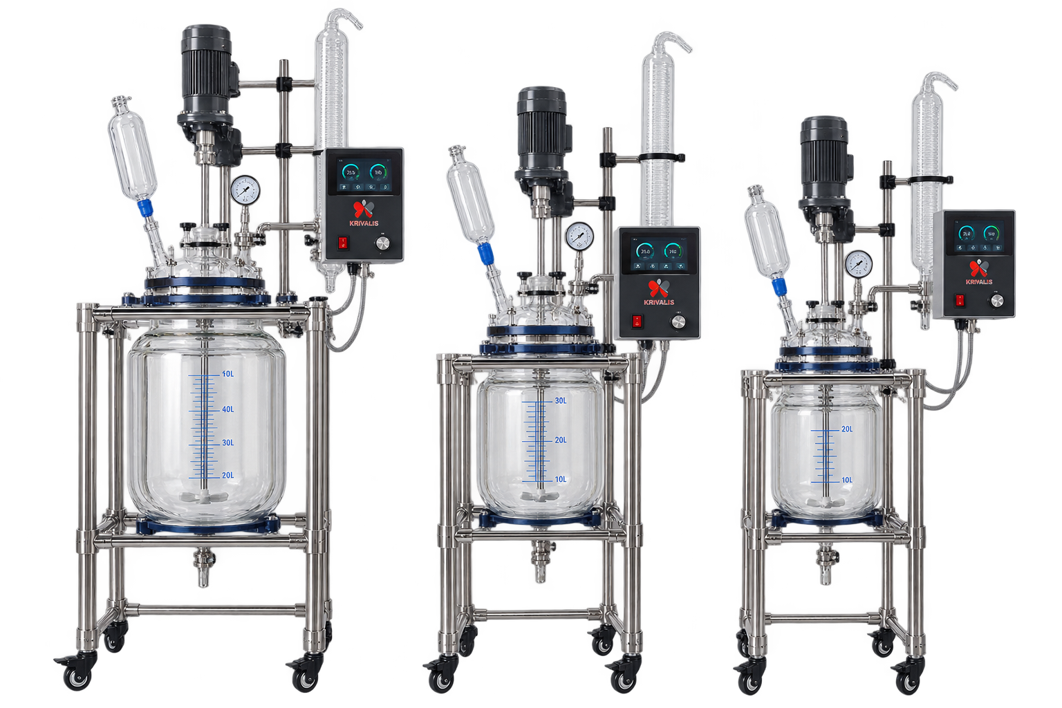
Glass reactors occupy a special place in the laboratory. Where a stainless steel autoclave gives you pressure and temperature readings, a borosilicate glass reactor lets you actually watch what the chemistry is doing — phase separation, colour change, crystal formation, foaming, catalyst settling, the exact moment a reaction turns. For process development and for teaching, that visibility is often worth more than an extra few bar of pressure headroom.
Krivalis supplies borosilicate 3.3 glass reactors from 1 litre to 100 litres, rated to 10 bar and 220°C, with overhead stirring and analogue or touch panel control. This guide explains where those figures come from, where the practical limits really lie, and how to operate a glass reactor safely.
Why Borosilicate 3.3 and Not Ordinary Glass
The 3.3 in borosilicate 3.3 refers to its coefficient of thermal expansion — approximately 3.3 × 10⁻⁶ per kelvin. Soda-lime glass, the material of bottles and window panes, sits close to three times that figure. The practical consequence is thermal shock resistance: a borosilicate vessel tolerates a rapid temperature change on the order of 100 K, where soda-lime glass may crack at a fraction of that.
Two further properties matter in a reactor. First, chemical resistance: borosilicate 3.3 is attacked only by hydrofluoric acid, hot concentrated phosphoric acid and strong hot alkali, which covers the great majority of organic and aqueous chemistry. Second, it is inert and does not leach metal ions into the product, which matters for trace-metal-sensitive work and for pharmaceutical intermediates where extractables have to be controlled.
What Visual Access Actually Buys You
Many process problems are invisible in a steel vessel until they show up as an off-spec batch. In glass they are immediately obvious:
- Phase behaviour: Whether a two-phase mixture has actually emulsified or separated, and how long settling really takes.
- Crystallisation: Onset of nucleation, habit of the crystals, and whether fines are being generated by over-agitation.
- Colour and clarity: Reaction end points, formation of tarry by-products, and carry-over of catalyst fines into the product.
- Foaming and gas evolution: Foaming during degassing or solvent change, and the rate at which gas is being released.
- Mixing quality: Whether the stirrer is actually turning over the whole charge, or channelling through the centre.
The Pressure and Temperature Envelope
A borosilicate glass reactor rated to 10 bar and 220°C is a genuinely useful range — it covers hydrogenation at moderate pressure, hydrogenolysis, carbonylation, polymerisation in solution and most autoclave work that does not require high hydrogen pressure.
It is important to understand that the two ratings are not independent. Glass strength falls as temperature rises, so the full 10 bar rating should be treated as available at the lower end of the temperature range and de-rated as you approach 220°C. For operating points that sit close to both limits at once, check with the manufacturer for the specific vessel rather than assuming the ratings multiply together.
Where a process needs 50 bar or 200 bar, glass is the wrong material and a sapphire or quartz reactor, or a steel vessel, is the correct choice. Glass is not a substitute for a high pressure autoclave — it is a different tool for a different job.
Construction of a Typical Glass Reactor
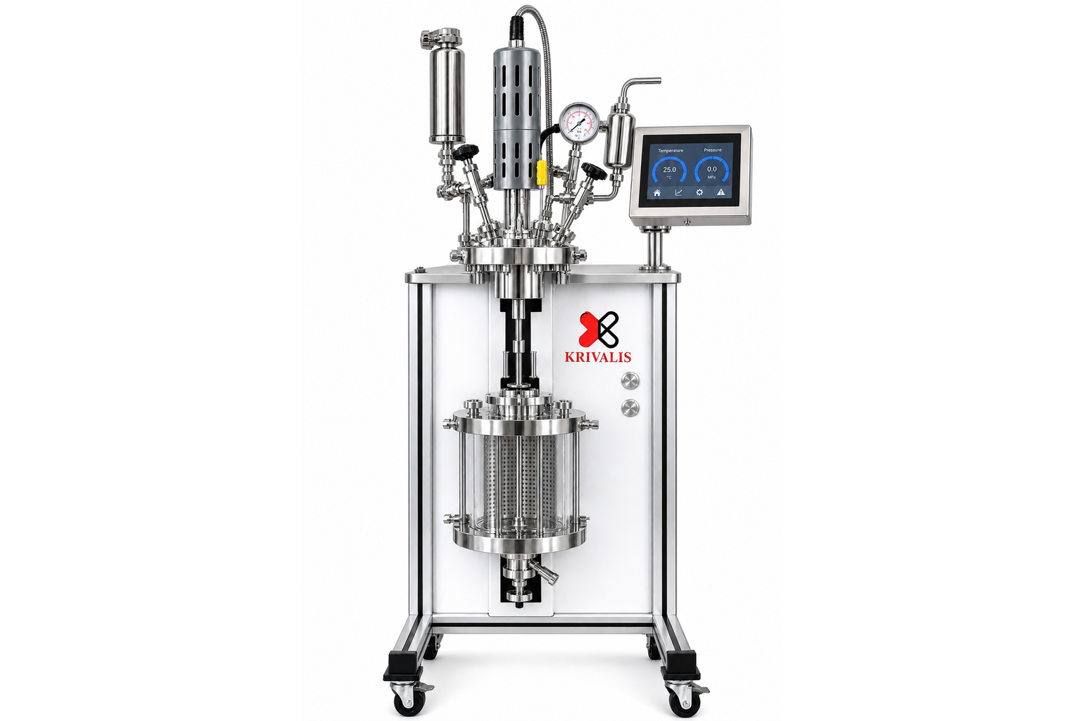
A Krivalis borosilicate reactor is built around a flanged glass vessel carried in a stainless steel or PTFE-coated frame on castors. The frame carries the vessel, the lid, the stirrer drive and the control panel as one unit, so the whole assembly can be moved and positioned without dismantling it.
- Vessel: Borosilicate 3.3 cylinder with a flat or dished bottom and a flanged neck. Graduations are printed on the vessel so the charge volume can be read directly.
- Closure: A flanged lid clamped to the vessel neck through a gasket. This is the single most important seal on the reactor, and the one most often disturbed during cleaning.
- Lid ports: Multiple necks for the stirrer, a condenser, a thermometer or sensor pocket, a gas inlet, a solid addition port and a spare. Port count drives how much instrumentation fits, so specify generously at the outset.
- Bottom outlet: A drain valve at the lowest point for discharge and for sampling. On larger vessels this is usually a PTFE-lined valve.
- Wetted materials: Borosilicate glass, PTFE and, where a metal component is wetted, borosilicate-compatible alloys. PTFE-faced seals and PTFE-sleeved stirrer shafts keep the product in contact with inert surfaces.
Agitation and Mixing
Glass reactors almost always use overhead mechanical stirring rather than magnetic stirring, because magnetic couplings become unreliable at larger volumes and higher viscosities. Typical impellers run from anchors and pitched-blade turbines for viscous or solid-laden charges, to Rushton turbines for gas dispersion.
Two practical points are worth more attention than they usually get. First, the stirrer shaft must be centred and the drive aligned; a glass reactor with a bent shaft will eventually damage the vessel neck. Second, run the stirrer at the lowest speed that achieves the required mixing. Excessive agitation abrades the glass, generates fines in crystallisations and can create a vortex that pulls gas into the liquid when you did not want it.
Thermal Control
Larger glass reactors are jacketed, with heat transfer fluid circulated from a heating and cooling circulator. The jacketed glass wall is mechanically weaker than an unjacketed one, which is one reason jacketed vessels are usually offered at lower pressure ratings than their unjacketed equivalents.
Borosilicate conducts heat far less well than stainless steel, and the wall of a 50 litre vessel presents a significant thermal resistance. As a result, heat-up and cool-down on large glass reactors are slower than the jacket fluid temperature suggests. When a process step is exothermic, this lag matters: the jacket can be calling for cooling while the bulk is still warming. Watch the bulk temperature, not the jacket setpoint.
Reflux, Condensation and Gas Handling
Most glass reactors run with a vertical condenser on one lid neck, and this is where a lot of operating detail lives. The condenser must be sized for the reflux ratio and the heat input, or solvent will be lost through the vent and the charge will concentrate without anyone noticing.
The vent path should never be closed off simply to reach a pressure target on a vessel that was not designed for it. For gas-consuming reactions, a gas inlet with a flow controller and a vent with a relief device is the correct arrangement. For inert atmospheres, a controlled bleed with a bubbler outlet is simpler and safer than trying to hold a static pressure in glass.
Vacuum and Inert Operation
Borosilicate reactors handle vacuum well, because the loading is compressive and glass is strong in compression. This makes them useful for solvent stripping, vacuum degassing and drying. The failure mode to avoid is pressure reversal during a sudden cool-down with a closed vent — a glass vessel can be collapsed by vacuum that no one intended to apply.
For oxygen- or moisture-sensitive chemistry, the vessel is purged and the inert gas is passed over the surface or sparged. Because everything is visible, glass is also the easiest way to confirm that a purge is complete.
Choosing a Volume
The working volume is normally 50 to 70 per cent of the nominal vessel volume, to leave headspace for foaming, gas evolution and stirring. Nominal sizes from 1 L to 100 L cover the normal path from bench development to pilot demonstration.
- 1 to 5 L: Route scouting, small-scale optimisation and teaching.
- 10 to 30 L: The common working size for process development and kilo-lab batches.
- 50 to 100 L: Pilot demonstration, where heat transfer and mixing behaviour begin to resemble production.
Safe Operation and Inspection
Glass under pressure is safe when it is intact and unsupported nowhere, and dangerous when it has been scratched. A few habits prevent almost all of the failures we see:
- Inspect before every run: Look for star cracks, chips at the flange face, and scuff marks. A damaged vessel should be retired, not rotated to the back of the shelf.
- Never scratch the glass: Do not use metal scrapers, and do not store stirrer shafts loose inside the vessel.
- Respect the flange: A gasket that has been over-compressed, or clamps that are unevenly tightened, load the glass unevenly. Tighten in a cross pattern.
- Fit a relief device: A rupture disc or relief valve on the vent path protects against overpressure from a runaway or an over-filled vessel.
- Use a shield and PPE: Operate behind a polycarbonate shield and wear eye protection. The failure mode of glass is sudden and energetic.
- Avoid thermal shock on the jacket: Do not step the circulator from 150°C to 5°C in one move on a large jacketed vessel.
Where Glass Reactors Fit
Glass is the right choice for moderate-pressure chemistry where observation pays for itself: process development, crystallisation studies, extraction and phase-behaviour work, polymerisation in solution, hydrogenation at moderate pressure, and academic teaching laboratories. It is the wrong choice for high-pressure hydrogenation above roughly 10 bar, for hydrofluoric acid service, and for hot concentrated alkali.
Conclusion
A borosilicate 3.3 reactor is at once the simplest and the most informative reactor in a laboratory. Its 10 bar and 220°C envelope covers a great deal of useful chemistry, and its transparency turns the vessel itself into an instrument. Specify the frame, ports and agitation around the process rather than the other way round, treat the flange seal and the glass surface with respect, and a well-chosen glass reactor will outlast several generations of steel ones.
Krivalis supplies borosilicate glass reactors from 1 L to 100 L alongside sapphire and quartz reactors for higher pressure optical work. Units can be configured with jacketing, overhead stirring, reflux condensers and analogue or touch panel control. See the Glass Pressure Reactor — Borosilicate in our catalogue, or contact our engineering team to discuss a configuration for your process.